I made a third level bootloader, that can load user standalone applications more quickly than StarterWare bootloader.
Can be adapted to work with all boards with AM335x TI microcontroller.
The bootloader can load applications with approximately 4.5MB/s depending to the size of fat cluster, the speed of uSD memory card (if a cluster of uSD filesystem is 16KB the speed is higher than one uSD card with 8KB cluster).
This bootloader is made to be loaded at address 0x87F80000(at end of beaglebone RAM memory), If you want to load this bootloader on another location please don't hesitate to write me.
Your application will be named APP.BIN to be loaded by this bootloader.
From here you can download the bootloader.
From here you can download the TI SDCard boot utility.
Friday, November 9, 2012
Thursday, November 8, 2012
AM335x SDK modified from StarterWare
After I bought a BeagleBone rev A6 boart and BeagleboneExpansion V2 CAP with a 800x480 display with capacitive touchscreen, I started to work with StarterWare available from TI.
On this SDK I try to create API's that will be very simple to use, like C#.
I try to arrange the drivers and API's and I added and translated some open source libraries.
The first result is a mix from AM335X_StarterWare_02_00_00_06 and AM335X_StarterWare_02_00_00_07.
On every version I will include a project that will show you how to use the SDK.
This SDK include the next files:
When is loaded from bootloader the USB host can't be enabled (will freeze when the USB controller is setup), to set up the USB host is necessary to hardware reset or power up the board without uSD card inserted, after a watchdog reset has the same issue.
I already posted the issue on TI.
Download source code and bin files from here.
Download SD card format utility from here.
Load the app and MLO file with SD boot card utility from archive, after this copy the APP.BIN file to uSD card.
On this SDK I try to create API's that will be very simple to use, like C#.
I try to arrange the drivers and API's and I added and translated some open source libraries.
The first result is a mix from AM335X_StarterWare_02_00_00_06 and AM335X_StarterWare_02_00_00_07.
On every version I will include a project that will show you how to use the SDK.
This SDK include the next files:
- API's
- Delay API.
- Gfx API.
- GPIO API.
- Interrupt API.
- LWIP API.
- MMCSD API.
- MMU API.
- PMIC API.
- RTC API.
- Capacitive touchscreen API(can read all five points).
- Resistive touchscreen API.
- TWI API.
- Uart API.
- USB API.
- USB mouse host API.
- USB MSC API.
- Applications
- Simple HTTP application(is a demo, respond only to "GET" command).
- Devices
- 24C TWI device driver.
- ADXL345 device driver.
- Library
- Bitmap decode library.
- PNG decode library.
- Jpeg decode library.
- MPEG1/2 decode library.
- Button library.
- Check Box library.
- Virtual Keyboard library.
- List Box library.
- Picture Box library.
- Progress Bar library.
- Scroll Bar library.
- Text Box library.
- System
- Cache.
- Dmtimer.
- Core Iit.
- CP15.
- Pin mux adc.
- Pin mux LCD.
- Pin mux MII.
- Pin mux MMCSD.
- Pin mux SPI.
- Pin mux TWI.
- Pin mux Uart.
- Sys timer(you can create infinite timers with precision approximate to reference timer7).
- Sys delay.
- Watchdog.
When is loaded from bootloader the USB host can't be enabled (will freeze when the USB controller is setup), to set up the USB host is necessary to hardware reset or power up the board without uSD card inserted, after a watchdog reset has the same issue.
I already posted the issue on TI.
Download source code and bin files from here.
Download SD card format utility from here.
Load the app and MLO file with SD boot card utility from archive, after this copy the APP.BIN file to uSD card.
Sunday, May 6, 2012
Xmega A1 Media Player development board
- Main controller ATxmega64A1/ATxmega128A1/ATxmega64A1u/ATxmega128A1u.
- On-board External 512KB SRAM memory ( AS6C4008 ).
- One or two onboard 24c EEPROM ICS up to 2Mb, or 23K serial RAM memory, or combined.
- One or two onboard uSD memory card sockets, with led to indicate activity of each uSD memory card.
- On-board usart to USB converter ( FT232RQ), with RX/TX activity led.
- On-board dedicated battery charger controller via USB connector ( MCP73871 ).
- On-board dedicated resistive touch screen controller ( AR1020 ).
- On-board dedicated RTC/64Bytes SRAM/128Bytes EEPROM circuit with backup high capacity capacitor ( MCP79410 ).
- On-board Ogg Vorbis/MP3/AAC/WMA/MIDI codec ( VS1053b ) with jack 3.5mm audio output ,3 pin connector audio input and connector for button style Microphone, with led activity monitor on xDCS, xCS and and DREQ pins.
- 320x240 TFT high quality display 8Bit bus mode ( MI0283QT-2 ) connected to external SRAM bus to increase speed of transaction using DMA working with him like a external SRAM.
- One 30 pin extension peripheral connector with bidirectional 8bit data bus, unidirectional 8Bit A0-A7 address bus,7 chip select signals, RW and RD signals and one IRQ line.
- On-board bus extension decoder to allow up to seven external peripherals directly accessed via external RAM bus ( 74LV138 ) and up to 256*7 external peripherals with external addresses decoders.
- One lateral push button user defined(like PWR/Back).
- One lateral push button reset function.
- PDI programing connector.
- JTAG debugging connector.
- 3V VLDO power regulator for all circuits, to power this board from LI-IO battery on entire range of voltage ( 3.2 to 4.2V and 5V from USB connector).
- 1.8V VLDO power regulator to power digital section on VS1053b circuit.
- On-board NOKIA or HUAVEI battery connector.
- Three pin connector to connect an external battery.
- 29 IO pins accessed via two lateral 26 pin connectors ( entire B and C port, pin port A2-A7 and D1-D7 ).
- Resistive divider to monitor the battery voltage.


- ATA high capacity hard disk shield.
- Secondary displays shield.
- Ethernet interface shield.
- Nand flash memory shield.
- Video sensor shield.
- Magnetometer shield.
- Gyroscope shield.
- Dedicated ADC shield to make oscilloscope.
- Video out encoder shield.
- Wireless communication shield.
- GSM communication shield.
- IR communication shield.
- Bluetooth communication shield.
- GPS shield.
- Motor stepper shield.
- Xbee shield.
This board will be delivered with a demo MP3 player project source code and a framework with library's and drivers special developed for this board.
Tuesday, February 7, 2012
How to setup avr studio 5 and 6 to use static library
I search entire internet for a explanation of error "undefined reference to" functions inside static library, but no explicit solution found.
For users that he cannot resolve this issue I will post two photos, how to set up the project to import functions from static libraries.


In this case the .h files is inside the "Directories" (photo2) and the .a files inside the "Debug" folder of each static library project(how is shown on bottom of first photo).
When you compile a static library the compiler generates a file named "libProjectName.a" on "Debug" folder, on top of first photo is shown how can be included the .a libraries, to include .a libraries is necessary to write the .a file name without "lib" and without ".a"inside a quote ("").
With this setup you can include and use static library.
Tuesday, January 24, 2012
Stereo digital audio spectrum analyzer V4.0
This version has multiple changes from the previous version, like:
V 4.0A is a version with 18 Bands + Two VU meters for right and left channels.
- Can handle stereo signals.
- Display format is 18+1+1( to display 18 bands of frequencies and Left Right signal level) .
- USB adapter for easy upgrade.
- Dedicated RTC with battery back-up.
- Added two usart connectors to create cascade spectrum analyzers( to create large display from boards like this ).
- A microcontroller twice faster that previous and multiple hardware advantages that increase speed of signal processing and display rendering.

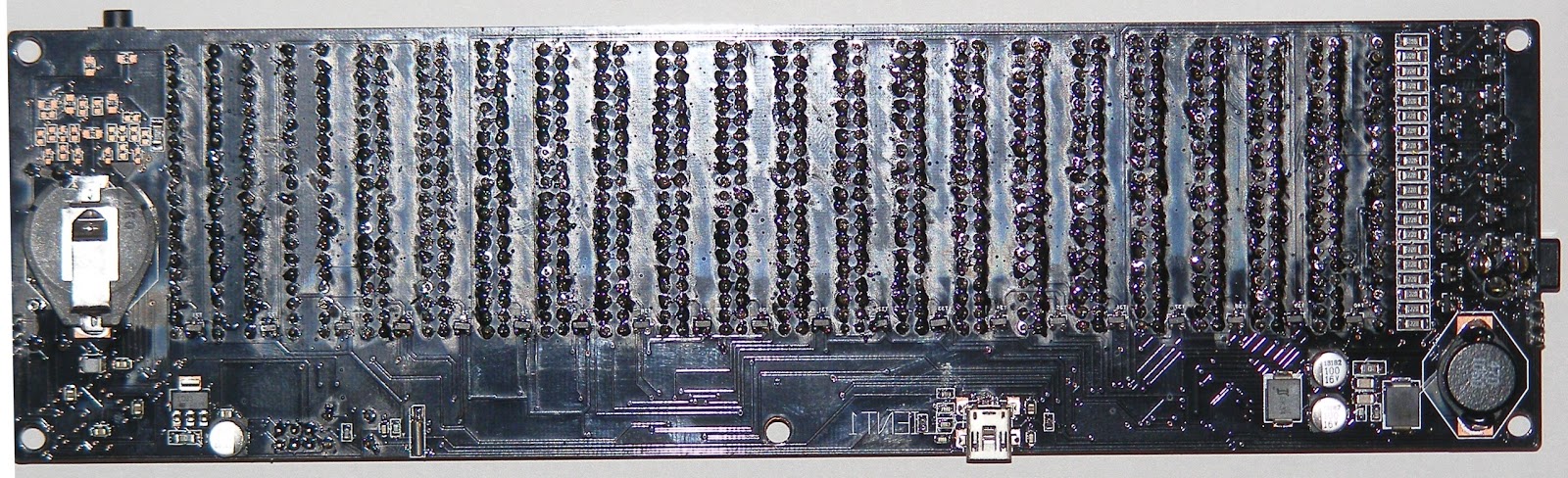
V 4.0B is a version with 20Bands.
A 3D presentation of Audio Spectrum Analyzer 4.0B:


Subscribe to:
Posts (Atom)