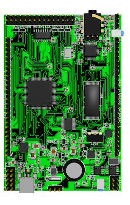
- Main controller ATxmega64A1/ATxmega128A1/ATxmega64A1u/ATxmega128A1u.
- On-board External 512KB SRAM memory ( AS6C4008 ).
- One or two onboard 24c EEPROM ICS up to 2Mb, or 23K serial RAM memory, or combined.
- One or two onboard uSD memory card sockets, with led to indicate activity of each uSD memory card.
- On-board usart to USB converter ( FT232RQ), with RX/TX activity led.
- On-board dedicated battery charger controller via USB connector ( MCP73871 ).
- On-board dedicated resistive touch screen controller ( AR1020 ).
- On-board dedicated RTC/64Bytes SRAM/128Bytes EEPROM circuit with backup high capacity capacitor ( MCP79410 ).
- On-board Ogg Vorbis/MP3/AAC/WMA/MIDI codec ( VS1053b ) with jack 3.5mm audio output ,3 pin connector audio input and connector for button style Microphone, with led activity monitor on xDCS, xCS and and DREQ pins.
- 320x240 TFT high quality display 8Bit bus mode ( MI0283QT-2 ) connected to external SRAM bus to increase speed of transaction using DMA working with him like a external SRAM.
- One 30 pin extension peripheral connector with bidirectional 8bit data bus, unidirectional 8Bit A0-A7 address bus,7 chip select signals, RW and RD signals and one IRQ line.
- On-board bus extension decoder to allow up to seven external peripherals directly accessed via external RAM bus ( 74LV138 ) and up to 256*7 external peripherals with external addresses decoders.
- One lateral push button user defined(like PWR/Back).
- One lateral push button reset function.
- PDI programing connector.
- JTAG debugging connector.
- 3V VLDO power regulator for all circuits, to power this board from LI-IO battery on entire range of voltage ( 3.2 to 4.2V and 5V from USB connector).
- 1.8V VLDO power regulator to power digital section on VS1053b circuit.
- On-board NOKIA or HUAVEI battery connector.
- Three pin connector to connect an external battery.
- 29 IO pins accessed via two lateral 26 pin connectors ( entire B and C port, pin port A2-A7 and D1-D7 ).
- Resistive divider to monitor the battery voltage.
- ATA high capacity hard disk shield.
- Secondary displays shield.
- Ethernet interface shield.
- Nand flash memory shield.
- Video sensor shield.
- Magnetometer shield.
- Gyroscope shield.
- Dedicated ADC shield to make oscilloscope.
- Video out encoder shield.
- Wireless communication shield.
- GSM communication shield.
- IR communication shield.
- Bluetooth communication shield.
- GPS shield.
- Motor stepper shield.
- Xbee shield.
This board will be delivered with a demo MP3 player project source code and a framework with library's and drivers special developed for this board.


